

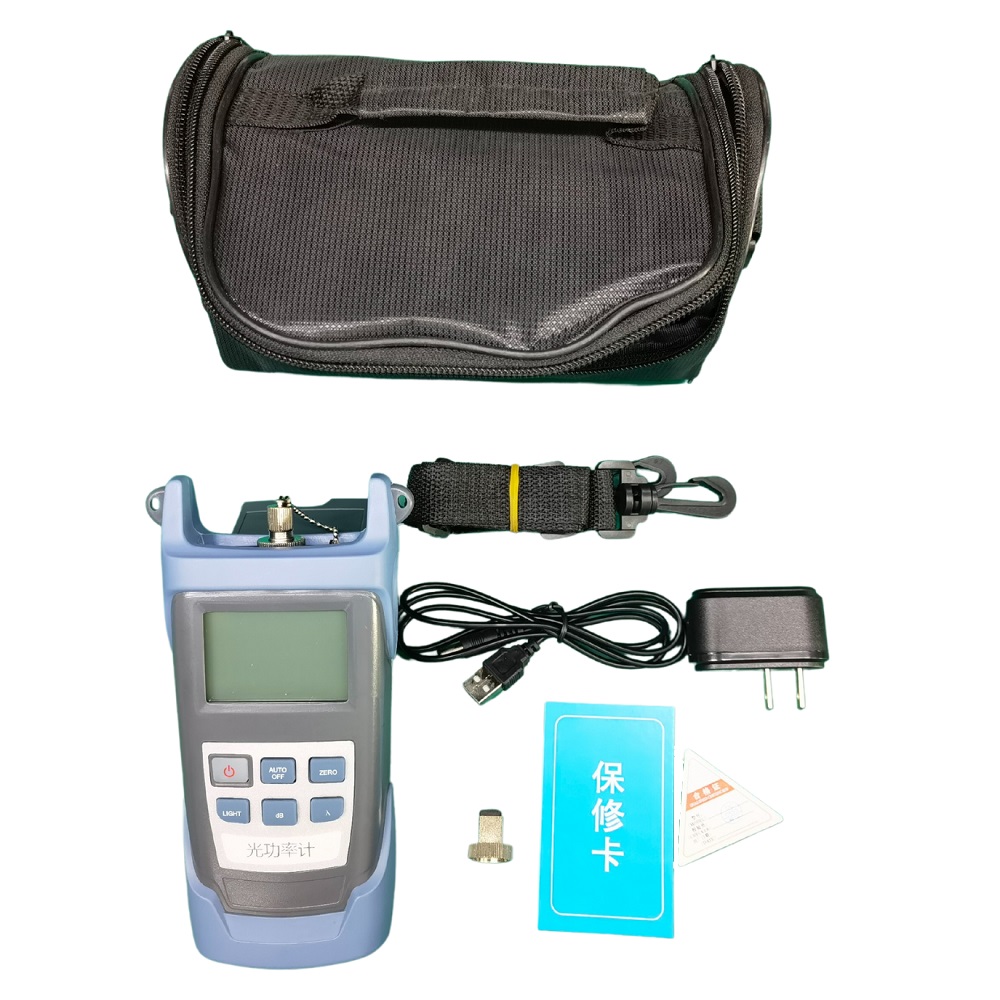
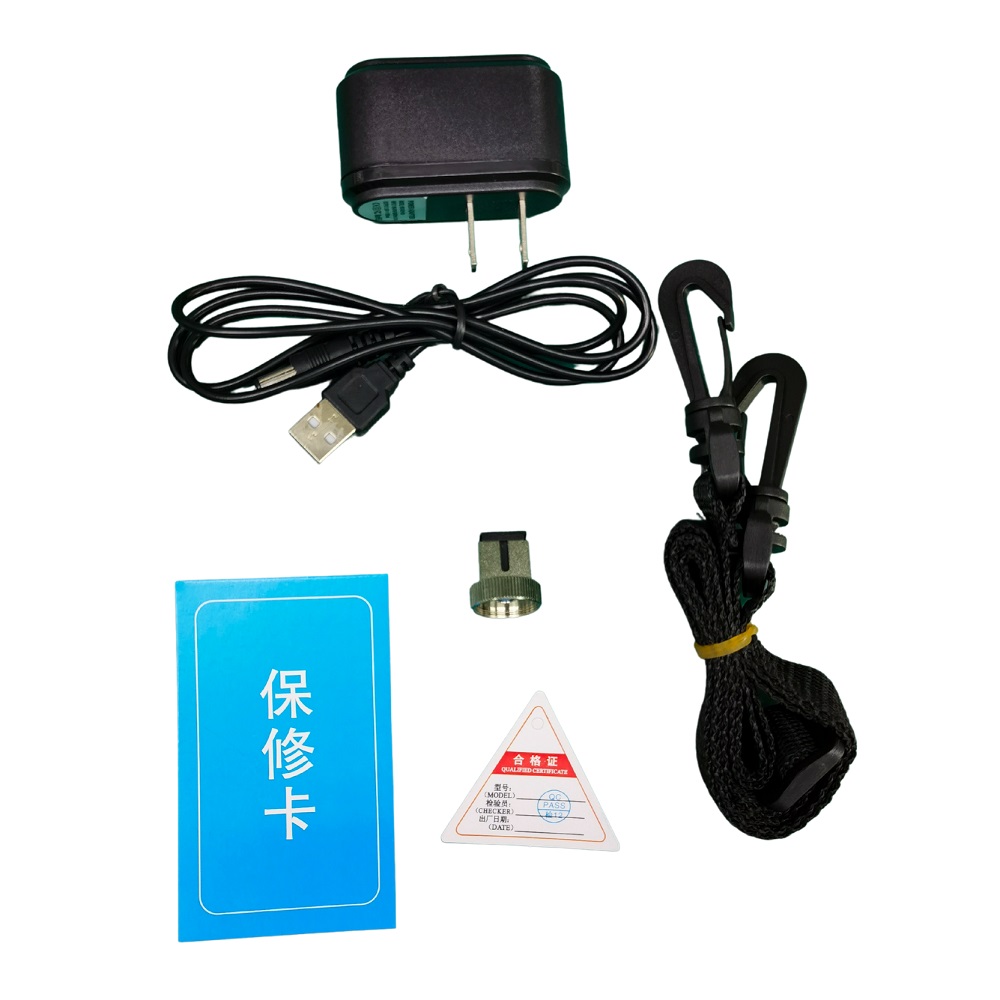

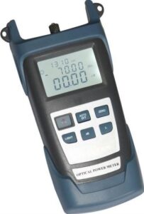
Product description
The Handheld Optical Power Meter is an accurate and durable portable meter specially designed for installation, operation and maintenance of fiber optic networks. It has a small form factor, backlight display with selectable switch and automatic shutdown function, ultra-wide optical power test range, precise test accuracy, user self-calibration function and general interface design, while linear indicators (mW) and nonlinear indicators (dBm) ) on the same screen.
Product Features
User self-calibration function
Linear (mW) and nonlinear indicators (dBm) are displayed on the same screen
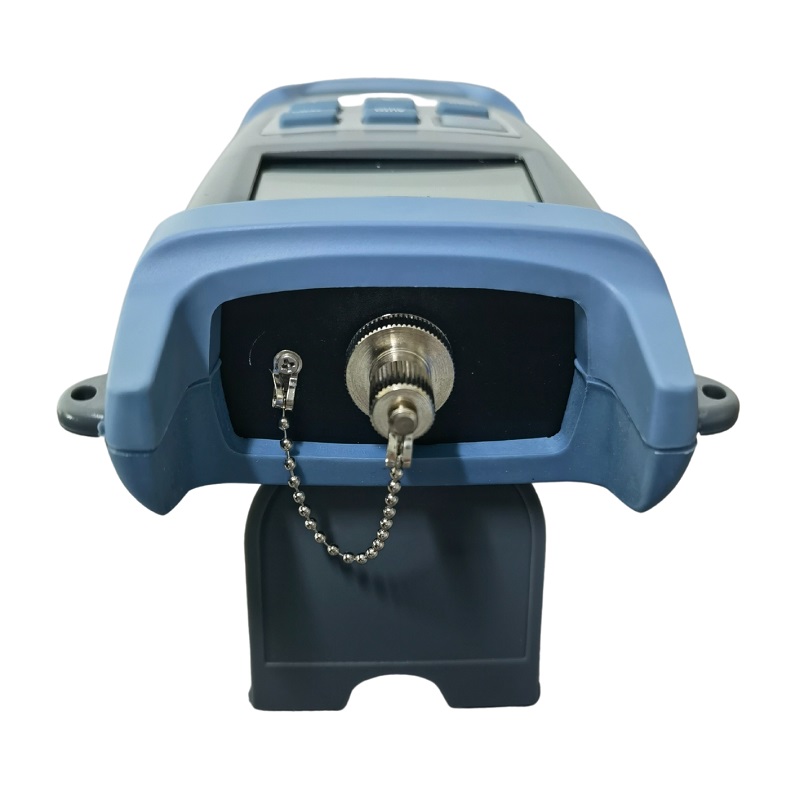
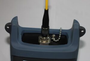
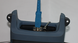
Unique FC/SC/ST universal interface (as shown in Figure 1, 2), no complicated conversion RequiredOptional automatic shutdown function
Backlit display with selectable on/off
Product Image:
|
|
Figure 1: Connection diagram with FC |
|
Figure 2: Connection diagram with SC |
Technical indicators
| Instrument model | Type A | Type B |
| Power measurement range | -70~+6 | -50~+26 |
| Probe Type | InGaAs | |
| Wavelength range | 800~1700 | |
| Uncertainty | ±5% | |
| Standard wavelength(nm) | 850、980、1300、1310、1490、1550、1625 | |
| Display resolution | Linear display: 0.1% Logarithmic display: 0.01dBm | |
| Operating temperature(℃) | -10~+60 | |
| storage temperature(℃) | -25~+70 | |
| Auto shutdown time(min) | 10 | |
| Battery continuous working time | Not less than 48 hours | |
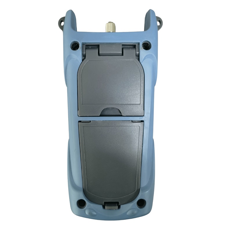
| Dimensions(mm) | 190×100×48 | |
| Power supply | Rechargeable lithium battery/3 1.5V dry batteries | |
| Weight(g) | 400 | |
Notice:
- Wavelength range: A standard working wavelength λ range is specified from λmin to λmax, and the optical power meter designed in this wavelength range can work under the specified index.
- Power measurement range: the range that can measure the maximum optical power according to the specified indicators.
- Uncertainty: The error between the test result of a certain optical power and the standard optical power test result.
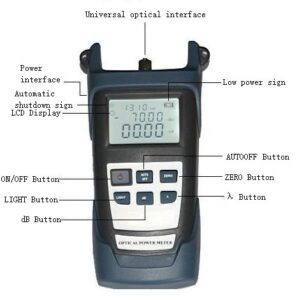
Function Description
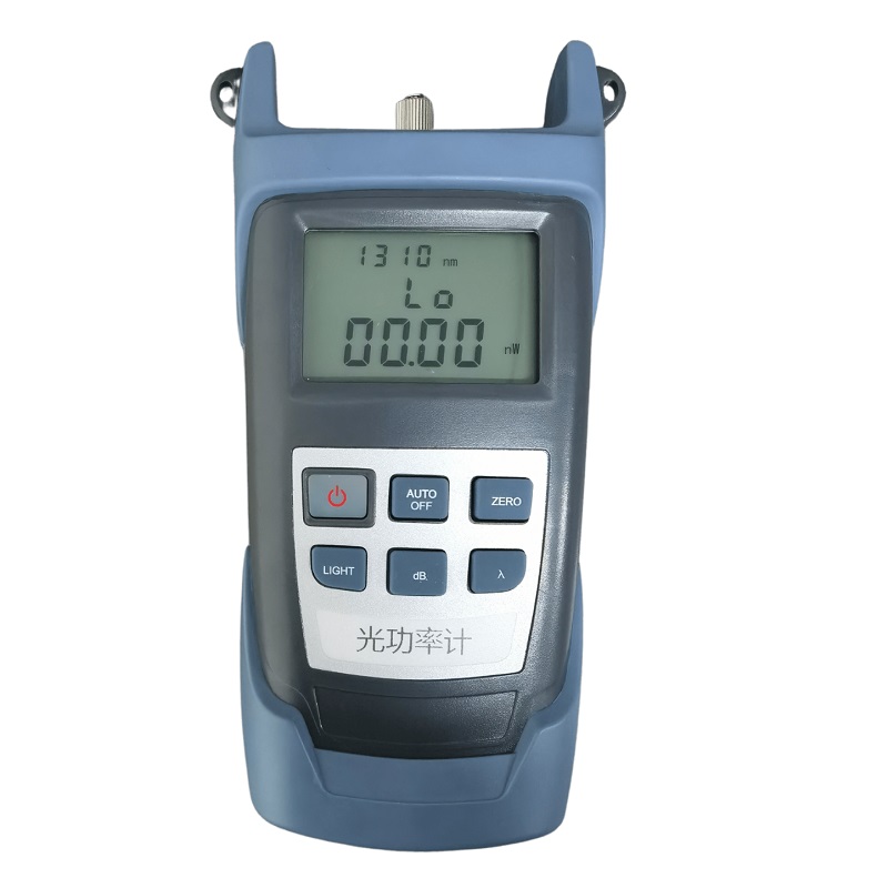
1.LCD display
The LCD displays the measured optical power value in the form of dB, dBm, mW, uW, nW; the set wavelengths are 850 nm, 980 nm, 1300 nm, 1310 nm, 1490 nm, 1550 nm, etc.
2.ON/OFF button
Press the ON/OFF key until the liquid crystal displays, then it can be turned on. At the same time, in the power-on state, press the key to turn off the machine.
3.dB button
At a set wavelength, a relative measurement of optical power is made.
4.ZERO button
Press this key to perform self-zeroing of the optical power meter.
5.λ button
Wavelength selection key, press this key to select different wavelengths, there are six wavelengths of 850 nm, 980 nm, 1300 nm, 1310 nm, 1490 nm, 1550 nm for selection, and the value will also be displayed on the LCD.
6.LIGHT button
Press this key to switch the LCD backlight on and off.
7.AUTOOFF button
Press this key to turn on or off the auto power off function.
Operation guide
power on/off
1.Press and hold the ON/OFF button on the front panel, the LCD displays, and the boot is completed.
2.Press the ON/OFF key on the instrument panel, the LCD has no display, and the optical power meter is turned off.
Absolute Optical Power Measurement
1.Turn on the optical power meter.
2.Set the measurement wavelength, select the measurement wavelength by the λ key, the default setting is 1310nm.
3.When connected to the measured light, the screen displays the current measured value, including the linear and nonlinear values of absolute power.
Relative optical power measurement
- Set the measurement wavelength.
- In the absolute optical power measurement mode, connect the measurement light to measure the current power value.
- Press the db key, the current optical power value becomes the current reference value (in dBm)
- Connect to another measurement light, and display the absolute optical power value and relative optical power value of the current measurement light.
Special function
There are three working modes, factory mode, user mode, working mode, usually always enter the working mode.
Factory pattern
Measured and calibrated at the factory
User modification mode
Press the λ+Light keys at the same time to enter the user mode, and the “nm” at the end of the first line is not displayed. If you press the λ+Light key again, it will exit the user mode and enter the working mode, and the “nm” at the end of the first line will be displayed.
Key combination table
| Function | button |
| Increase 0.05 | Light |
| Reduce 0.05 | dB |
| Save | Zero |
| Switch wavelength | λ |
| Factory reset | λ+ Zero |
Remarks: If the user’s own calibration has deviation or operation error, you can press the “λ” and “Zero” keys at the same time in the “User Modification” mode to restore the power meter to the factory state.
Automatic shutdown function
Press the AUTOOFF button to turn on/off the automatic shutdown function. When the shutdown function is turned on, the shutdown symbol is displayed on the upper left of the screen, and if no button is pressed for 10 minutes, it will automatically shut down.
LED backlight on/off function
In working mode, press LIGHT to turn on/off the backlight. When the backlight is turned on, a small sun sign will be displayed on the upper left of the screen, indicating that the backlight is on.
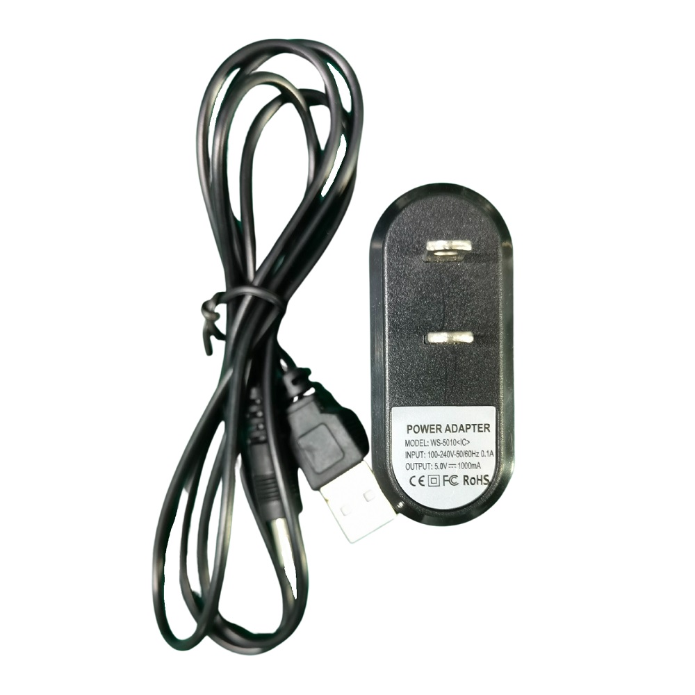
Lithium battery rechargeable function
During normal operation, the battery indicator does not display; when the battery is low, the battery indicator flashes once every second, and will automatically shut down after ten flashes; at this time, directly connect the charger with the meter to charge (as shown in the right As shown in the picture), it can save the trouble of replacing the battery and related costs.
Maintenance
- Always keep the end face of the sensor clean to be free of grease and pollution, do not use dirty, non-standard adapter joints, and do not insert the end face with poor polishing surface, otherwise the end face of the sensor will be damaged and the performance of the entire system will be greatly reduced.
- Stick to one adapter whenever possible.
- Once the optical power meter is not in use, immediately cover the dust cap to protect the end face clean and prevent measurement errors caused by long-term exposure to dust attached to the air.
- Carefully insert and unplug the optical adapter connector to avoid scratching the port.
Periodically clean the sensor surface. When cleaning the sensor surface, use a special cleaning swab to gently wipe in a circular direction.
Common malfunctions
| failure performance | possible reason | Solution |
| LCD show weak | Insufficient power | Charge |
| No display on boot | Insufficient power/other | Reboot/Charge |
| LCD display data remains the same or changes slightly | Optical adapter connector faulty or dirty
cloudy/display locked |
Detecting Optical Adapter Connector Connections
correct; clean sensor end face |
Quality assurance
We do not recommend users to repair the smart handheld optical power meter by themselves.仪表1.The warranty period is eighteen months from the date of shipment. Our company will promise the materials and workmanship of all its products, and the warranty period is valid within 18 months from the date of shipment. When the purchased products are found to have quality problems during this period, our company will make corresponding repairs or replacements. However, in no event will our company’s liability exceed the purchase price of the product.
- If there is a problem in the use of the instrument, the solution according to the common fault prompts still cannot be solved, the user is not allowed to open the case without authorization, please contact the marketing department of our company or local agents.
- For quality failures caused by production defects, our company is responsible for free repair or replacement of products.
This warranty applies only to normal use of the meter without damage or misuse.
The product warranty does not cover problems/failures caused by:
- Unauthorized repairs or modifications to the meter.
- Improper use, negligent use or accident, etc.
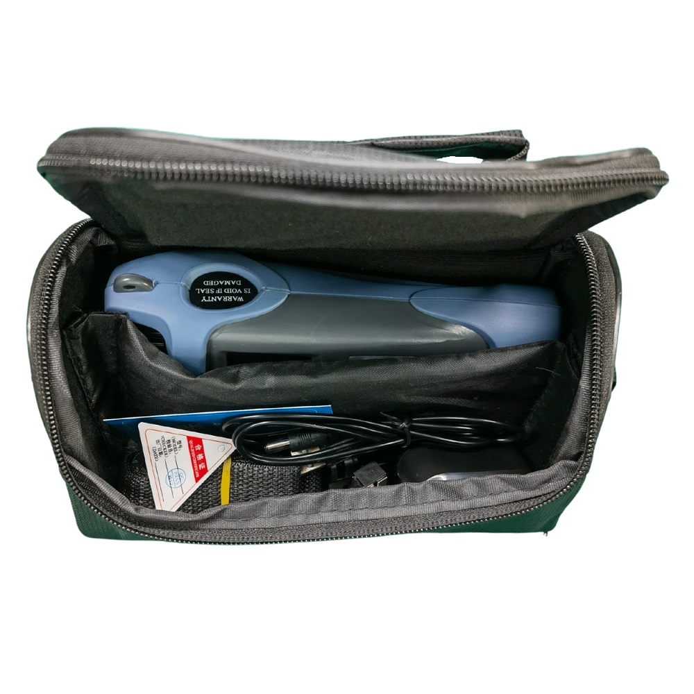
Along with my product, there is a warranty card of our company. Please fill it in and send it back to our company together with a copy of the invoice, so that we can have a record of the root cause when we need to maintain, technically innovate, calibrate, etc. to your instrument in the future.
Appendix: Fiber Loss Measurements
Step 1 Setting the base (reference) value
Turn on the optical power meter and use the λ key to select the correct working wavelength.
Turn on the light source (emission source), select the correct wavelength and let it stabilize (this process takes about 1-2 minutes).
Choose a fiber patch cord for connecting the light source, we call it the launcher patch cord, and clean the connector of the launch patch cord. Note: The fiber used for the source jumper must be the same fiber used for the fiber link under test.
Connect the light source (transmitter source) to the optical power meter with the source jumper.
Use to get the optical power value at this time.
Note: The power value measured at this time should be close to the set value of the light source (emission source) itself. If there is a large deviation, please pay attention to carefully clean each connection end face or replace the emission source jumper in time.
Press the dB key of the optical power meter, the reading of dB at this time is 0.00, and at the same time, the measured optical power value is set as the reference (reference) value.
Note: After zeroing, the number of digits after the decimal point will change slightly, which is normal.
Step 2 Fiber link loss measurement
Keep the source jumper connected to the light source (transmitter).
Connect the light source (transmitter source) to the respective and required fiber optic links.
NOTE: Clean all connection end faces, including required fiber optic adapters.
The displayed reading is the loss of the fiber link under test, in dB (the current absolute optical power value is displayed in dBm).